簡單的LED電源項(xiàng)目電路

簡單的LED電源項(xiàng)目電路 A power source for simple LED projects
本文引用地址:http://www.czjhyjcfj.com/article/169373.htmLED's are great display tools. Their prices have decreased to a point where they are replacing more conventional light sources. In one sense their characteristic need for low voltages is an advantage e.g compatibility with I.C drives, but this voltage requirement can also be a disadvantage. I wanted to light some LED's in a simple sign application, nothing fancy, but I needed to decrease the utility line voltage to a LED-compatible value for this application.
The line voltage can be reduced in various ways, via dropping resistor, a transformer, a brick power supply, a capacitor etc. A dropping resistor wastes considerable power and generates heat. A brick power supply must be adapted to the particular design needs, i.e a specific voltage and current and also may have an expense associated with it that is undesirable for a simple circuit. A transformer can be bulky, weigh a lot and may be expensive.
A capacitor can act as a voltage dropping component and in this instance, was chosen to light the static LED display shown below. The considerable drop in voltage from the line (117 v.a.c) down to approximately 2-1/2 volts a.c results in an almost negligible power loss in the capacitor(s). It is simple, low cost and small.
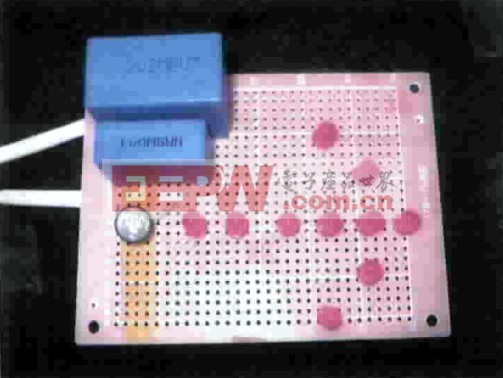
The 10 LED's were lit using the following circuit...
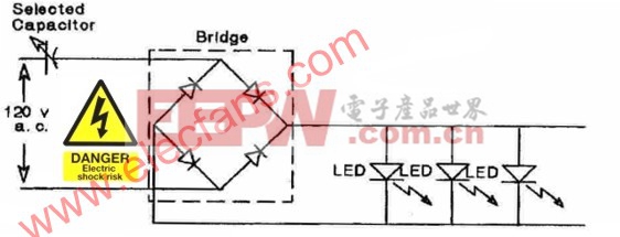
figure 2
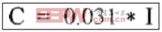
The capacitor value may be computed via the following empirical formula. This formula is valid for the circuit shown in Fig.2:
 (1)
(1)
Where C is in uFd and I is in miliamperes. A design current of 10 mA per LED was selected. Thus for ten LED's, 100mA is the total current. Inserting this current value into the formula, yields a capacitor value of 3.1uFd.
To achieve this value, two capacitors connected in parallel were used. Recall that the total capacitance of capacitors connected in parallel is simply the arithmetic sum of the individual capacitors:

Thus:
![]()
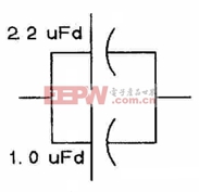
figure 3
If it becomes necessary to use capacitors connected in series to achieve a desired total capacitance, the formula for this computation is:
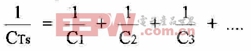
For two capacitors in series, it may be easier to calculate the total series capacitance via:
![]()
To achieve a desired total capacitance, it may be necessary to use a series-parallel connection of three capacitors. Empirical formula (1) was derived by measuring currents and voltages for various quantities of LED's (up to 30) connected into the circuit shown in Fig 2. The capacitors must be low loss, non-polarized units with voltage ratings equal to or greater than 200 volts.
Transformer voltage dropping circuit
If instead of using capacitors, it is desired to power LED's with a transformer, the low voltage, rectified sine wave ideally should be applied to each LED via a dropping resistor. This enables the forward current to be adjusted to a value that does not overdrive the LED. In lieu of using dropping resistors, if the rectified voltage is carefully selected via a judicious choice of transformer, the output of a rectifier may be applied directly to one or more LED's connected in parallel.
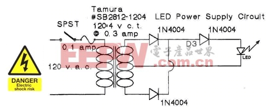
figure 4
The Tamura transformer has a 4 volts c.t secondary. This value just supplies sufficient voltage to generate 14mA for one LED. For 10 LED's or greater, omit D3.
Circuit comparison
Comparing the two approaches, the capacitor voltage dropping circuit is smaller, lighter in weight and varying the capacitor value enables the user to obtain a desired current value for each LED. The transformer approach, yields a circuit where the transformer provides isolation between the LED's and the line voltage. Both circuits are nominally low in parts cost.
Parts
The components used in gathering data where purchased from Mouser Electronics:
- 2.2 uFd = PHE840MZ7220MF14R ($2.52)
- 1.0 uFd = PHE840MY7100MD16R ($0.93) (275 Volts)
- Tamura transformer #SB2812-1204 ($3.53)
- 1N4004 diodes ($0.08 each)
The bridge rectifier and LED's were purchased from All Electronics:
- LED-1 (T1-3/4 Red LED) ($0.10 each)
- FWB-15, 1-1/2 amp, 400 PIV Bridge Rectifier ($0.50 each)
- Perf Board
Acknowledgments: My thanks to Mr. Oscar Ramsey for his testing, data gathering and construction efforts.


評論