汽車熱限制器的烙鐵

汽車熱限制器的烙鐵 Auto Heat Limiter for Soldering Iron
本文引用地址:http://www.czjhyjcfj.com/article/197727.htm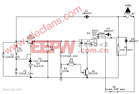
Wattage of load | 10W | 18W | 25W | 35W | 65W | 80W |
Value of R5 (in ohms) | 330 | 180 | 136 (68+68) | 100 | 56 | 44 (22+22) |
Wattage of R5 (in watts) | 01 | 02 | 02 | 04 | 05 | 6.5 |
Usually a soldering iron takes a couple of minutes to get adequately heated up to melt the solder, after which the heat generated is much above the requirement and is wasted. Moreover, excessive heat decreases the life of the bit and the element, causing serious damage to the components.
The above circuit solves this problem in a simple and inexpensive way and could be used to various types of loads up to 80watts.
How it works
Once the main is switched on, an approximate 15v drop of the positive half cycle across R5 is detected and supplied to Q1 (SL100 or D313), which acts as a voltage regulator. Zener diode D2 together with diode D3 (yellow LED) stabilizes the emitter voltage of Q1 at 13.2Vdc, which is then delivered to the relay circuit built around Q2 and C3. Capacitor C3 charges through the base-emitter path of Q2 and causes the relay to actuate, which in turn allows both the half cycles of the AC mains to flow through diode D6 and R5 to the load to heat it up at a normal rate.
After a certain lapse of time (about 2 minutes preset) C3 saturates and Q2 stops conducting through the relay, thus switching on series diode D5 to allow only half of the Ac cycle through the load.
After switching off the system, C3 discharges very slowly through R2 and R3. Before C3 gets completely discharged, if the power is switched on again, C3 takes a shorter time to reach the saturation level, thus switching series diode D5 much earlier than the preset time to prevent double heating of the load.
However, if the circuit is switched on only after a few seconds of switching off, C3 gets no time to discharge and the relay does not actuate at all. Moreover, if the relay circuit fails due to any reason and Q2 does not conduct, no harm is done to the load because in that case D5 remains in series with it. Thus the circuit offers complete protection to the load.
As stated earlier, the given value of C3 gives a delay of 2 minutes. However, a 1000mfd capacitor can also be used to produce a 4.5-minute delay. R5 maintains a drop of about 15V across itself. So for use in different load conditions its value changes as shown in Table 1.
The whole circuit can be mounted on a PCB and fitted in an adapter case (7.6cm X 5.1cm X 6.4cm) and used as a mains plug. Since R5 gets heated up during the operation, it should be kept well isolated from the other components.
Components List
R1 - 220 ohms
R2 C 10K
R3 C 150K
R4 C 82K
(all resistors should be 5% close tolerance)
C1- 100 uf, 25V dc working electrolytic
C2 C 100 uf, 25V dc working electrolytic
C3 C 220 uf, 16V dc working electrolytic
(advisable to use close tolerance Caps. to obtain correct timings)
D1, D4, D5, D6 C IN4007
D2 C 12V 400mw, Zener diode
D3 C Yellow LED
RLY1 C 6V, 300 ohms DC relay
Q1 C SL100 or D313
Q2 C BC108


評論