3V供電的LED驅逐艦電路

General
本文引用地址:http://www.czjhyjcfj.com/article/169409.htmThere are many 9V chaser circuits that seem to waste about 7V when driving LEDs that are only about 2V. This project is unique, because it uses only two inexpensive alkaline battery cells totaling 3V for power. Since most of the waste is eliminated, the cells last a long time.
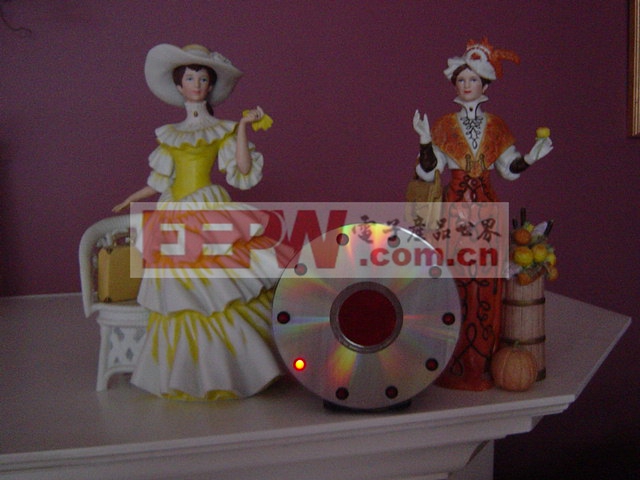
Unlike the other circuits, this one flashes the LEDs for only about 30ms each, further extending the battery life. For user convenience, it has a stepper speed control and a brightness control. At slower speeds and with reduced brightness, the battery life is further extended considerably. Mounted in a circle, the LEDs appear to rotate as they step from one to the next.

Specifications
Battery: Two alkaline cells (AA size were used in the prototype)
Battery Life: AA cells C cells D cells
Minimum speed and brightness 8 months 2 years 4.9 years
Medium speed and brightness 6 months 1.5 years 3.6 years
Maximum speed and brightness 2 weeks 1.5 months 3.6 months
Stepper speed: 2 LEDs/sec to 2 revolutions/sec
Brightness: Controlled with Pulse Width Modulation, from very dim to 161mcd (very bright)
Pulse Width Modulation frequency: 1.4KHz very bright to 6KHz very dim
LED current: 15mA pulses, reduced to 10.5mA at maximum Pulse Width Modulation
LED voltage drop: 1.76V (measured, not rated) @ 10.5mA
Minimum battery voltage (total of both cells): 1.24V, circuit is running but LEDs are not lit
1.6V, LEDs are very dim at maximum brightness
2.0V, LEDs reach almost full brightness, battery replacement is recommended.
Radio interference: None
Circuit Description
The 74HC Cmos ICs are rated for a 2V to 6V power supply for high-speed logic circuits. They continue to operate at a much lower voltage but no longer meet high-speed logic specifications. To reach high speeds, their output current can momentarily exceed 400mA (low voltage drop) but thermal considerations limit maximum continuous output current to 20mA. Perfect for driving LEDs!
IC2 is a 10 stage Johnson counter/decoder. On the rising edge of each clock pulse its outputs step one-at-a-time. It drives the anode of each conducting LED toward the positive supply.
IC1a is a standard Cmos inverter Schmitt-trigger oscillator with C3 and C4 totaling 800nF for a very slow step rate. R2 is the speed control pot with R1 limiting its maximum speed. It clocks IC2 and feeds the inverters/drivers. D1 and R3 reduce its output high time to 30mS.
IC1d, IC1e, IC1f and IC1b are paralleled inverter/drivers for a low output voltage drop and drive the emitter of T1 to ground.
IC1c is another standard Cmos inverter Schmitt-trigger oscillator. R5 is its Pulse Width Modulation control and with D3 performs dimming of the LEDs. D2 and R4 extend the PWM’s maximum pulse width.
T1 is a transistor that is used as a PWM switch. R7 limits maximum LED pulse current.
C1 bypasses the battery’s supply voltage at low frequencies and C2 bypasses at high frequencies.
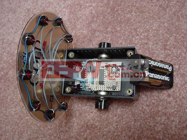
Construction
The ten LEDs mount on a Compact-Disc which is glued to a plastic box with contact cement. The box houses the Veroboard circuit in its lower main part with the battery holder in its lid. Multiconductor ribbon cable joins the LEDs to the circuit. The pots mount on the sides of the box.
Parts List
1 IC1 CD74HC14N or SN74HC14N High-speed Cmos, Schmitt-trigger hex inverters
1 IC2 CD74HC4017N or SN74HC4017N High-speed Cmos, decade counter-decoder
1 T1 2N3904 or 2N4401 NPN transistor
10 LEDs MV8191 High brightness wide angle red LED (less than 2V)
3 D1 to D3 1N4148 or 1N914 Silicon diode
2 R1, R3 100K 1/4W resistor
1 R2 1M Linear taper potentiometer (speed)
1 R4 330K 1/4W resistor
1 R5 1M Audio taper (logarithmic) potentiometer (brightness)
1 R6 680 1/4W resistor
1 R7 22 1/4W resistor
1 C1 100uF/10V or 100uF/16V Electrolytic capacitor
1 C2 0.1uF/50V or 0.1uF/100V Ceramic disc capacitor
1 C3 330nF/63V Metalized poly capacitor
1 C4 470nF/63V Metalized poly capacitor
1 C5 1nF/100V Metalized poly capacitor
2 misc.Alkaline battery cells 1 misc. Plastic box
1 misc.Battery holder 3 misc. Vinyl feet for box
1 misc. Compact Disc 2 misc. Knobs for potentiometers
1 misc. Hole plug for the CD’s center hole 1 misc. 9 to 11 conductor ribbon cable
Notes
1) The ICs are manufactured by Texas Instruments, and others.
2) The LEDs are manufactured by Fairchild Semiconductor.
3) Above manufacturers offer free samples.

DIY機械鍵盤相關社區:機械鍵盤DIY


評論