模擬開(kāi)關(guān)降低繼電器的功耗-Analog Switch Low

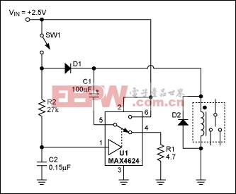
Figure 1. Analog switch lowers relay power dissipation.
Power consumed by the relay coil equals V2/RCOIL. The circuit lowers this dissipation (after actuation) by applying less than the normal operating voltage of 5V. Note that the voltage required to turn a relay on (pick-up voltage) is greater than that required to keep it on (dropout voltage). The relay shown has a 3.5V pick-up voltage and a 1.5V dropout voltage, yet the circuit allows it to operate from an intermediate supply voltage of 2.5V. Table 1 compares the relay's power dissipation with fixed operating voltages across it, and with the Figure 1 circuit in place.
Table 1. Power Dissipated By Relay
| Voltage | Current | Total Power Dissipation |
| 5V (normal operating voltage) | 90mA | 450mW |
| 3.5V (pick-up voltage) | 63mA | 221mW |
| 2.5V (circuit of Figure 1) | 45mA | 112mW |
When you close SW1, current flows in the relay coil, and C1 and C2 begin to charge. The relay remains inactive because the supply voltage is less than its pick-up voltage. The RC time constants are such that C1 charges almost completely before the voltage across C2 reaches the logic threshold of the analog switch. When C2 reaches that threshold, the analog switch connects C1 in series with the 2.5V supply and relay coil. This action turns on the relay by boosting the voltage across its coil to 5V (twice the supply voltage). As C1 discharges through the coil, the coil voltage drops back to 2.5V minus the drop across D1, but the relay remains on because that voltage is above the relay's dropout voltage (1.5V).
Component values for this circuit depend on the relay characteristics and the supply voltage. The value of R1, which protects the analog switch from the initial current surge through C1, should be sufficiently small to allow C1 to charge rapidly, but large enough to prevent the surge current from exceeding the peak current specified for the analog switch. U1's peak current is 400mA, and the peak surge current is IPEAK = (VIN VD1)/(R1 + RON), where RON is the on-resistance of the analog switch (typically 1.2Ω). The value of C1 depends on the relay characteristics and on the difference between VIN and the relay's pick-up voltage. Relays that need more turn-on energy require larger C1 values.
The values for R2 and C2 are selected to allow C1 to charge almost completely before C2's voltage reaches the logic threshold of the analog switch. In this case, the time constant C2R2 is about seven times C1(R1 + RON). Larger C2R2 values increase the delay between switch closure and relay activation.
A similar version of this article appeared in the December 20, 2001 issue of EDN magazine.


評(píng)論