Adjusting the output voltages

Adjusting the output voltages of the MAX8660/MAX8661
Abstract: TheMAX8660/MAX8661PMICs (power management ICs) have the most common output voltages as standard features. Additionally, output voltage values are programmable through a serial interface. This application note offers several options for changing the output voltage values of the step-down converter to support uncommon default voltage requirements.
Introduction
The MAX8660/MAX8661 are highly integrated PMICs (power-management ICs). The high efficiency and small size of these devices make them ideal for portable battery-powered equipment. To maintain a small overall solution, the MAX8660/MAX8661 does not require external feedback components to set the regulator output voltages. Instead, Maxim offers the most common output voltages as standard features on these devices. If these standard output-voltage options are incompatible with your system, this application note explains how to change the step-down output voltages.
Support documents for this application note
- MAX8660–MA8661 data sheet
- AN4515_MAX8660-MAX8661 Adjusting V1-4.xls
Increase the V1 and V2 output voltage with external resistors
Figure 1B and Figure 1C show two methods to increase the REG1 and/or REG2 output voltage. Follow the steps in the tab titled "REG1-2 Output Voltage Inc." in the AN4515_MAX8660-MAX8661 Adjusting V1-4 spreadsheet to find the resistor values and output voltage accuracy of the two solutions:
- The circuit of Figure B uses a single external resistor. However, the spreadsheet shows that the output accuracy is poor with this circuit when the required output voltage increase above the standard output voltage is large (> 100mV). If the converter's switching waveforms exhibit excessive jitter or pulse grouping compared to the standard configuration, add a feed-forward capacitor in the range of 10pF to 100pF. To find the best capacitor for your application, start with a 33pF and make adjustments from there.
- The circuit of Figure 1C uses two external resistors to increase the standard output voltage. Accuracy can be very good with this circuit, but it comes with a trade-off: increased feedback current. To find the optimal solution for your application, use the spreadsheet to experiment with the target feedback current and external resistor values. If the converter's switching waveforms exhibit excessive jitter or pulse grouping compared to the standard configuration, add a feed-forward capacitor in the range of 10pF to 100pF. To find the best capacitor for your application, start with a 33pF and make adjustments from there.
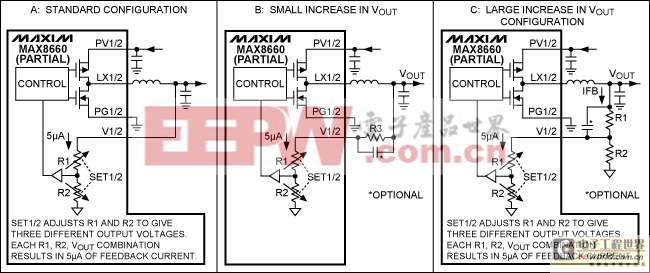
Figure 1. Increasing the output voltage of REG1 and 2.
Decrease the V1 and V2 output voltage with external resistors
Figure 2B and Figure 2C show two methods to decrease the REG1 and/or REG2 output voltage. Follow the steps in the tab titled "REG1-2 Output Voltage Dec." in the spreadsheet to find the resistor values and output voltage accuracy of the two solutions:
- The circuit of Figure 2B uses two external resistors (R3 and R4) to decrease the standard output voltage. To decrease the output voltage, an "always-on" reference is needed. In this case we use V8. If accuracy is critical, the V8 reference can be substituted with a voltage reference like the MAX6029. Lastly, this configuration requires a minimum load on the regulator (R5) to ensure that the output does not drift up to the reference.
- The circuit of Figure 2C adds a disconnect circuit to eliminate the load on the reference voltage when the step-down regulator is shutdown.
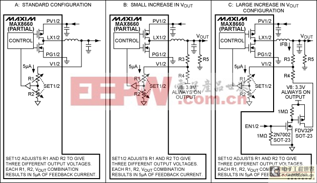
Figure 2. Decreasing the output voltage of REG1 and 2.
Increase the V3 and V4 output voltage with external resistors
Figure 3B shows how to use two external resistors to increase the REG3 and/or REG4. Follow the steps in the tab titled "REG3-4 Output Voltage Inc." in the spreadsheet to find the resistor values and the output voltage accuracy of this solution.
- The circuit of Figure 3B uses two external resistors (R1 and R2) to increase the standard output voltage. As shown in the spreadsheet, R_1 and R_2 increase the output voltage over the entire I2C-adjustable output-voltage range. If the converter's switching waveforms exhibit excessive jitter or pulse grouping compared to the standard configuration, add a feed-forward capacitor in the range of 10pF to 100pF. To find the best capacitor for your application, start with a 33pF and make adjustments from there.
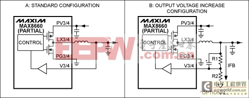
Figure 3. Increasing the output voltage of REG3 and 4.
Decrease the V3 and V4 output voltage with external resistors
Figure 4B shows how to decrease the REG3 and/or REG4 output voltage (same technique as in Figure 2). Follow the steps in the tab titled "REG3-4 Output Voltage Inc." in the spreadsheet to find the resistor values and output voltage accuracy of the two solutions:
- The circuit of Figure 4B uses two external resistors (RFBI and RFBV) to decrease the standard output voltage. To decrease the output voltage, an "always-on" reference is needed. In this case we use V8. If accuracy is critical, the V8 reference can be substituted with a voltage reference like the MAX6029. Lastly, this configuration requires a minimum load on the regulator (RLMIN) to ensure that the output does not drift up to the reference.
- To eliminate the load on the reference voltage that occurs in Figure 4B when the regulator is shutdown, use the disconnect circuit scheme shown in Figure 2C.
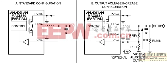
Figure 4. Decreasing the output voltage of REG3 and 4.
Please contact the Maxim factory with output voltage questions that are beyond the scope of this application note. We appreciate your interest in the MAX8660/MAX8661, and have several other options for adjusting output voltages.

評論