DDS直接數字合成2 - 任意信號

為了生成任意信號,DDS 依賴于兩個主要技巧。
本文引用地址:http://www.czjhyjcfj.com/article/202401/454848.htmLUT
第一個 DDS 技巧是 LUT(查找表)。 LUT 是一個表格,用于保存我們想要生成的模擬信號的形狀。
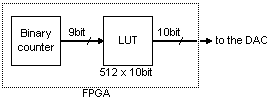
在FPGA中,LUT是作為blockram實現的。 在上圖中,我們使用了 512x10 位 LUT,它通常適合一個或兩個物理 FPGA 模塊。
正弦波
最常產生的信號形狀是正弦波。 它很特別,因為它有兩個對稱性,可以很容易地利用它們來使 LUT 看起來更大。
在正弦波中,第一個對稱性是sin(α)=sin(π-α)。
假設我們的 “my_DDS_LUT” blockram 是這樣實例化的
wire [9:0] LUT_output;

blockram512x10bit_2clklatency my_DDS_LUT(.rdclock(clk), .rdaddress(cnt[8:0]), .q(LUT_output));
我們只需要在半個周期后以相反的方向訪問 LUT 即可利用第一個對稱性。
blockram512x10bit_2clklatency my_DDS_LUT(.rdclock(clk), .rdaddress(cnt[9] ? ~cnt[8:0] : cnt[8:0]), .q(LUT_output));
因此,現在我們只將一半的波存儲在模塊中,但其內容在輸出信號的每個周期中使用兩次。 從某種意義上說,LUT 顯示為 1024x10 位(使用第二種對稱性,我們得到 2048x10 位)。
請注意,我們使用一個塊“blockram512x10bit_2clklatency”,它提供具有兩個時鐘延遲的數據(因為一個時鐘延遲塊框速度較慢)。 如何做到這一點取決于FPGA供應商(Altera將使用LPM,而Xilinx將使用原語)。
讓我們將 LUT 重寫為一個單獨的模塊,利用兩個正弦對稱性。
// sine lookup value module using two symmetries
// appears like a 2048x10bit LUT even if it uses a 512x10bit internally
// 3 clock latencymodule sine_lookup(input clk, input [10:0] addr, output reg [16:0] value);
wire [15:0] sine_1sym;  // sine with 1 symmetry
blockram512x16bit_2clklatency my_quarter_sine_LUT(     // the LUT contains only one quarter of the sine wave
    .rdclock(clk),
    .rdaddress(addr[9] ? ~addr[8:0] : addr[8:0]),   // first symmetry
    .q(sine_1sym)
);

// now for the second symmetry, we need to use addr[10]
// but since our blockram has 2 clock latencies on reads
// we need a two-clock delayed version of addr[10]
reg addr10_delay1;
always @(posedge clk) addr10_delay1 <= addr[10];
reg addr10_delay2; always @(posedge clk) addr10_delay2 <= addr10_delay1;
wire [15:0] sine_2sym = addr10_delay2 ? {1'b0,-sine_1sym} : {1'b1,sine_1sym};  // second symmetry

// add a third latency to the module output for best performance
always @(posedge clk) value <= sine_2sym;
endmodule
請注意,sine_lookup模塊總共有 3 個時鐘延遲(兩個來自模塊,一個來自末尾的注冊輸出)。
時鐘延遲的好處是可以流水線操作,并從FPGA中獲得最大可能的性能。 不要忘記,這需要運行至少 100MHz。
此外,我們還將 blockram 的輸出寬度從 10 位增加到 16 位(如果在我們的特定 FPGA 模塊中未使用,則 6 位會丟失,因此我們不妨實現它們)。 我們將在第 4 部分中充分利用多余的部分。
為了有效地使用我們新制作的“sine_lookup模塊”,我們可以簡單地編寫
reg [10:0] cnt;
always @(posedge clk) cnt <= cnt + 11'h1;
wire [16:0] sine_lookup_output;
sine_lookup my_sine(.clk(clk), .addr(cnt), .value(sine_lookup_output));
wire [9:0] DAC_data = sine_lookup_output[16:7];   // for now, we drop the LSBs to feed our DAC
                                                  // (since it takes only 10 bits)
我們從DAC得到一個很好的正弦波。
上一篇:DDS直接數字合成1 - 簡介


評論